
Ground Rod System and Electrolytic Ground Electrode Comparison
The primary purpose of a grounding system is to provide a low impedance path for currents to the earth. The effectiveness of a ground system corresponds to its capability of dissipating currents of numerous wave shapes to the earth. Various current wave shapes include DC, 60 Hz power frequency, high-frequency switching, and lightning surges.
Design goals for a ground system do not rest solely on ground system resistance. Acceptable ground system resistance and ground system impedance are both important goals when determining the effectiveness of an installed system.


Grounding System Resistance
The National Electric Code (NEC), Motorola R56, and relevant IEEE standards refer to grounding system resistance values to determine the horizontal and vertical components of a grounding system. The vertical component of a grounding system includes a ground electrode(s) of various depths. And, the horizontal component includes ground conductor installed a minimum of 30” below grade level or below the frost line, whichever is greater. The best grounding system design consists of the correct selection and installation locations of both vertical and horizontal components.
Grounding System Impedance
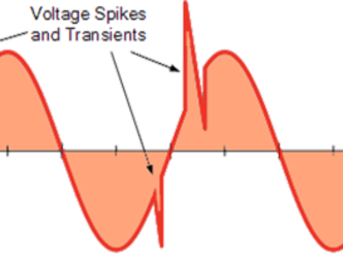
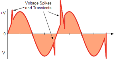
Grounding system impedance, on the other hand, plays a particularly important role when dealing with high-frequency transient events. The most relevant examples are lightning and switching surges. These transient currents are characterized by a fast-rising “front” impulse wave followed by a decaying low frequency “tail” wave. A grounding system appears to such transient events as an impedance rather than resistance. Although this is a well-known phenomenon, none of the existing standards have any specific ground system impedance requirements for lightning frequency nor is any particular frequency defined for the lightning energy.
The formula for determining ground system impedance:

The ground system impedance increases as the source frequency increases. The rate of increase depends on the ground system design and conductor routing.
Typical Telecommunications Facility Case Study
In the following case study, a typical telecommunication site is analyzed in specialized integrated grounding software to differentiate between grounding system resistance and impedance at various frequencies. In addition, the effectiveness of TerraDyne® Electrolytic Grounding Electrodes are analyzed at both 60 Hz power frequency and high frequency during lightning strikes.
Soil Resistivity Data
To determine the resistivity of the soil, the Wenner four-point measurement method corresponding to IEEE Std. 81 was utilized. The Wenner 4-point measurement test employs 4 test probes, spaced apart from each other at equal distances.
The resulting data is entered into specialized integrated grounding software that accurately calculates the earth resistivity at various depths. A two layer soil resistivity model is created around the facility.
As observed from the soil resistivity model, the upper soil resistivity is 141,023 Ω-cm down to the depth of 7.09 feet. It is also noted that lower soil resistivity is 24,442 Ω-cm. The soil has higher resistivity value at the top layer as compared to the lower layer.

Two-Layer Soil Resistivity Model
System Modeling
The grounding model was developed with reference to the designed grounding system using solid copper conductor buried at a minimum 30” below grade. All below grade grounding conductors are to be encompassed in a 2”×4” bed of TerraFill® soil enhancement material. A vertical TerraDyne® electrolytic ground electrode and twelve (12) 5/8” × 10’ copper clad ground electrodes constitute the ground electrode system.

Grounding System Impedance Analysis
| Source Current Frequency | Ground System Resistance (R) Ω | Ground System Reactance due to Inductance (XL) Ω | Overall Ground System Impedance (Z) Ω | Remarks |
|---|---|---|---|---|
| DC | 4.16 | Not Applicable | 4.160 | Only the ground system resistance is applicable when source current is DC. Since the frequency of the system is zero, overall ground system impedance is equal to calculated ground system resistance |
| 60 Hz Power Frequency | 4.1607 | 0.002 | 4.1607 | Overall ground system impedance for 60 Hz power frequency is identical to DC voltage.
This is the standard ground system impedance requirement for 60 Hz power fault current. |
| 100 kHz | 4.786 | 2.9882 | 6.64 | Typical lightning frequency is 100 kHz+ up to 1 MHz |
| 300 kHz | 6.5353 | 7.1750 | 9.7 | |
| 1 MHz | 11.7354 | 16.86 | 20.54 |
Comparison
Standard Ground Rod Electrode vs. Electrolytic Ground System
For a given 2-layer soil model, the comparison was made between the ground system resistance/impedance offered by a standard 20-foot ground rod and a vertical 20-foot electrolytic ground electrode.
| Source Current Frequency | Grounding Type | Ground System Resistance (R) Ω | Ground System Reactance due to Inductance (XL) Ω | Overall Ground System Impedance (Z) Ω | Remarks |
|---|---|---|---|---|---|
| DC | 20′ Standard Ground Rod | 54.08 | Not Applicable | 54.08 | Only the ground system resistance is applicable when source current is DC. Since the frequency of the system is zero, overall ground system impedance is equal to calculated ground system resistance |
| 20′ Electrolytic Ground Rod | 14.74 | Not applicable | 14.746 | ||
| 60 Hz Power Frequency | 20′ Standard Ground Rod | 54.0811 | 0.0013 | 54.08 | Overall ground system impedance for 60 Hz power frequency is identical to DC voltage.
This is the standard ground system impedance requirement for 60 Hz power fault current. |
| 20′ Electrolytic Ground Rod | 14.746 | 0.0019 | 14.74 | ||
| 500 kHz | 20′ Standard Ground Rod | 54.3662 | 10.7037 | 55.4 | Typical lightning frequency is 100 kHz+ up to 1 MHz |
| 20′ Electrolytic Ground Rod | 17.3113 | 15.196 | 23.03 |
At 60 Hz power frequency, there is a 72.74% reduction in ground system impedance offered by TerraDyne® electrolytic ground electrode over the standard ground rod.
At 500 kHz high frequency, there is 58.4% reduction in ground system impedance offered by TerraDyne® electrolytic ground electrode over the standard ground rod.
These results correspond only to the considered 2-layer soil resistivity value. The final reduction percentages will depend upon the analyzed 2-layer soil resistivity model for any specific site. Model results, as well as extensive real-world experience, show that TerraDyne® electrolytic ground electrodes provide a truly advantageous low impedance path for both 60 Hz power and 500 kHz high frequency. This makes electrolytic ground electrodes the preferred ground system component for both 60 Hz power frequency and lightning protection applications.
If you have an existing or planned facility, be sure to give ALLTEC a call or email.
If you have an existing or planned facility, be sure to give ALLTEC a call or email. We can make sure your operation is the safest possible facility, backed by our team of dedicated risk-mitigation experts. If you have a current or future project that needs grounding/bonding solutions, surge suppression or lightning protection please contact ALLTEC at either 1-828-646-9290 or online-info@alltecglobal.com
Rev. 20150527
