
What is soil resistivity?
Simply put, soil resistivity is a measurement of how much the soil being sampled resists electric current. Typically, the resistivity varies with depth in soil, moisture, temperature and chemical content.
Why is soil resistivity important?
When considering a grounding system installation, the site’s soil is where the foundation is built. A sturdy foundation is the key to building a proper grounding system; just as it is essential with any building project. Potential variations in resistance to electricity makes it imperative to conduct soil resistivity testing prior to designing a grounding system. For example, if you attempt to ground a system in rocky soil that is poorly conductive, an electrical surge may not be safely transferred to ground. It could loop back and damage or destroy the structure you were trying to protect! If you have completed your testing and know the soil has high resistivity, additional measures can be added to your grounding system to ensure success.
Isn’t all soil the same?
Soil quality varies greatly with depth and over wide areas. Soil classification provides only a rough approximation. Many factors can change the resistivity measurements of soil some of which include moisture, temperature, type, and depth.
- Moisture tends to enhance soil conductivity. Typically, the greater the moisture content, the lower the resistivity. This is considered good.
- Temperature is especially important in areas with colder climates. Below freezing temperatures have detrimental effects on a grounding system not designed specifically to accommodate freezing temperatures. At below freezing, clay or cement-based backfill materials, which rely on water as their primary conductor, can solidify and therefore fail.
- Soil types with high organic content are usually a good conductor. It tends to hold more moisture. Whereas, sandy soils will lose moisture faster and have lower amounts of electrolytes. The worst soils are often rocky or volcanic ash and have almost no moisture at all.
- Depth and type of surface soil may change. For example, the site has a nice organic mix of soil on the top; but as you go deeper, it turns to clay. Or, you may have clay on the top before turning to rocky soil. These variations impact soil resistivity values.
How is soil testing accomplished?
There are two main methods of testing soil resistance: the Wenner method and the Schlumberger method. The most common and reliable one is the Wenner four-point test method. Both methods space their electrode probes evenly corresponding to the soil depth being investigated. However, the methods use different formulas to calculated resistivity values. The test is conducted by placing four test probes into the ground spaced equal distances apart across the raw land where the grounding system is required. A ground meter is attached to the probes to collect the numbers necessary to calculate the soil resistance using Ohm’s law. Soil values can range from 500 Ω cm with large amounts of electrolytes to over 1 million Ω cm in sandy dry soil. Five tests (four sides and a diagonal) are conducted to provide acceptable results.

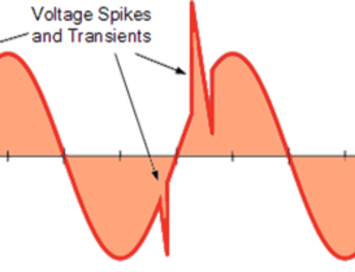
Soil Testing Graph

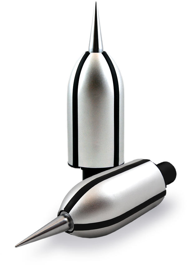
Soil Resisitivity Testing Meter
What should you keep in mind when looking into a grounding system?
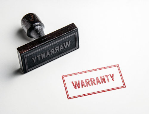
Ideally, you want a location with the lowest possible resistance available. However, poor soil conditions can be overcome with a more elaborate grounding system, with cost and available space being the primary factors to consider. Poor grounding is second only to improper wiring as the leading cause of equipment malfunction. The need for low-resistance grounding systems is crucial. In fact, equipment warranties may be invalidated at sites where specific ground systems performance goals are not met. This is really a step you do not want to skip over, as your whole system is based on it.
What is system grounding with earth electrodes?

Figure 2
The “Earth Electrode,” also known as ground electrode, provides an electrical connection to earth. The impedance of an electrode determines how quickly and at what potential energy is equalized. The resistance value is determined by the resistivity of soil with which these electrodes are in contact. Current must pass through the soil to the assumed earth potential of 0 Ω.
When an object is grounded, it is forced to assume the same zero potential as the earth. If the potential of the grounded object is higher or lower, current will pass through the grounding connection until the potential of the object and earth are the same. The earth electrode is that connection path to the earth.
The resistance of the electrode, measured in ohms, determines how quickly and at what potential energy is equalized. Upper and lower soil levels typically have different inherent resistivity. Grounding materials and electrodes can take advantage of lower resistivity soil conditions in one or the other layer to minimize materials, maximize performance, and meet ground system resistance goals.
Even is you think you know what your soil is made of, it is always a good idea to have testing done before installing any type of grounding system.
Our engineering team is ready to help you not only test your soil, but determine that grounding designs that will best suit your individual needs. Give us a call today at 800.203.2658 or you can email us at online-info@alltecglobal.com.
