
Protecting Variable Frequency Drives with Surge Protection Devices (SPDs)
Sophisticated and highly susceptible microprocessor-based electronics and data communication networks are integrated across every sector of today’s fast-paced business world. Preserving these mission-critical systems from the damages of surges, spikes, and transients ensure that these systems are protected from equipment destruction, disruption in service, and from costly downtime. How to properly stage these SPDs can be as important as actually deciding to purchase them.
Overall, properly installed surge protective devices reduce the magnitude of random, high energy, short duration electrical power anomalies. These occurrences are typically caused by atmospheric phenomena (such as lightning strikes), utility switching, inductive loads, and internally generated overvoltages.

Protection of Drives
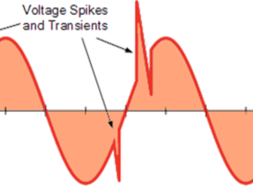
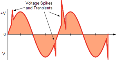
The use of various types of drives to control motors is widespread. The purpose of the drive is to increase the efficiency or to manage the speed of the motor being controlled. Through various processes and control mechanisms, the drive often reshapes the sinewave to provide a signal to the motor that allows for greater efficiency or varies the frequency of the signal to control the speed of the motor.
Due to the action of the drive, the power quality of the electrical environment can be compromised. That is, the drives can create voltage surges and harmonics on the system.
There are various technologies available that aid in correcting these issues. This application note focuses on applying surge protective devices (SPDs) to a drive system to mitigate the damage that can occur due to voltage surges while considering the effects of the harmonics on the surge protective device.
Application of SPDs
To aid in the description of the application of SPDs to a drive system, please refer to Figure 1.
This figure illustrates a typical drive layout. The incoming power is usually delta configured (3 phases and ground).
Often the incoming voltage is 480 V, but other voltages may be used. The incoming power is usually stepped down to a lower voltage (typically 120 Vac) that provides power to the control circuit. The control circuit contains sensitive electronics. Once the power is acted upon by the drive the output is fed to the motor.
As noted, there are five opportunities for protecting the typical drive system–each are labeled with a circled number and are described below.

At this location, a parallel connected, voltage responsive circuitry device is appropriate–one without frequency responsive circuitry. Frequency responsive circuitry is not recommended for this location since this location is typically more susceptible to impulse transients as opposed to ring wave transients.
The inverter input is one of the most sensitive and critical areas of the drive itself. It’s this location where care must be taken and a proper survey conducted. You may install a parallel connected, frequency responsive circuitry device provided you have confirmed no additional capacitors have been installed to mitigate harmonic currents within this drive.
If addition capacitors are installed, a parallel connected, voltage responsive circuitry device is appropriate at this location–one without frequency responsive circuitry. Frequency responsive circuitry would not be recommended for this location due to the high harmonic content that necessitated the installation of additional capacitors. Installation of frequency responsive circuitry devices at this location will lead to failure of the SPD.
The control circuit contains sensitive electronics that can be damaged by the environment created by the drive or by surges from external sources. Protection at this location is essential.
Since a step-down transformer isolates this circuit and feeds sensitive electronics, a series connected SPD with frequency responsive circuitry is recommended for this location.
Protecting the immediate drive output is recommended when the length of the connection between the drive and the motor is longer than 50 ft (15 m) or if the connection is routed along an external wall or outdoors.
One reason for protecting at the immediate output when the length of the connection to the motor is long is due to reflected waves that can occur as the signal (often higher frequency) from the output of the drive reaches the motor and is then reflect back and forth between the drive and the motor. This action can create “voltage piling” – the reflected voltage adds to the nominal voltage and other reflected waves. The SPD will aid in reducing the voltage peaks of the reflected waves.
Long lengths and those routed along external walls or doors can cause reflected waves. Reflected waves occur as the signal (often higher frequency) from the output drive reaches the mother and is reflected back and forth between the drive and the motor. this action creates “voltage piling.” The reflected voltage adds to the nominal voltage and other reflected waves. The SPD will aid in reducing the voltage peaks of the reflected waves.
More importantly, if the connection between the drive and the motor extends outdoors along a path that is exposed to the environment or close to the building’s steel structure, protection at this location is essential to diminish the effects of direct lightning or induced voltage surges due to nearby lightning. These surges can cause damage to the drive, even if protection is provided at the motor input.
At this location, a parallel connected, voltage responsive circuitry device is appropriate–one without frequency responsive circuitry. Frequency responsive circuitry is not recommended for this location due to the high harmonic content of the signal due to the normal operation of the drive. Installation of frequency responsive circuitry devices at this location will lead to failure of the SPD. Utilizing a voltage responsive circuitry device at this location will eliminate this possibility.
Protecting the motor input is an essential step in protecting the drive system. Providing protection at this location prevents surge damage due to events propagated from the drive output to the motor input. Protecting this location aids in extending the life of the motor as the SPD helps to prevent damage to the windings and bearings of the motor due to surges.
Further, if the connection between the drive and the motor extends outdoors along a path that is exposed to the environment or close to the building’s steel structure, protection at this location is important to diminish the effects of direct lightning or induced voltage surges due to nearby lightning. These surges can cause damage to the motor, even if protection is provided at the drive output.
At this location, a parallel connected, voltage responsive circuitry device without frequency responsive circuitry is appropriate. Frequency responsive circuitry is not recommended for this location due to the high harmonic content of the signal due to the normal operation of the drive. Installation of frequency responsive circuitry devices at this location will lead to failure of the SPD. Utilizing a voltage responsive circuitry device at this location will eliminate this possibility.
Explore our surge protection devices for your variable frequency drive needs!
The ultimate goal of our approach is to keep sites and systems operating safely and reliably. DynaShield® Surge Protection Devices incorporate “Frequency Responsive Circuitry” technology years ahead of any other devices on the market today. Utilizing proprietary electro-chemical encapsulation,DynaShield® SPDs dissipate large amounts of surge energy to prolong service life.

