
ALLTEC Solutions for Traffic Control Applications
Traffic control sites often experience damage to electronic systems during thunderstorm activity. Various approaches towards external and internal grounding and surge protection are usually experimented with at one time or another by those responsible for site preparation, traffic control enclosure installation, signal and peripheral equipment installation, and maintenance and repair.
Highly variable philosophies, access to equipment and supplies, and levels of understanding, often yield a hodge-podge of ground loops, rods and wires, surge protection devices (SPDs), and connection schemes at any single location. This situation is multiplied across the spectrum of remote electronic enclosure sites that fall within the jurisdiction of any particular responsible authority, such as a Department of Transportation (DOT). This document has been prepared as a template, to assist DOT personnel in understanding and implementing successful site solutions.
There is no perfect time to repair or replace malfunctioning equipment, but sending a crew out in the middle of the night into the teeth of a thunderstorm is a decidedly imperfect scenario that happens all too often. Control failures cause traffic accidents and require overtime pay for traffic officers and other municipal employees. The cost of maintenance, repair, and replacement of increasingly sensitive and expensive electronic equipment strain budgets already stretched thin.

As a global leader in the design, manufacture, and installation of lightning protection, grounding systems, and transient voltage surge suppression technology, ALLTEC has the solutions you need. Founded in 1991, we have focused continuously on innovating new technology, improving product quality, and enhancing customer service.
We offer a comprehensive facility protection approach to solving the world’s most difficult lightning, grounding, and power quality problems. This expertise translates directly to successful solutions for remote electronic system enclosures and sites, and specifically “Traffic Control Applications.”
ALLTEC’s Protection Pyramid® — A Three-Step Program to Success
 Bonding is simply a matter of connecting all of the electrical systems and metallic masses within a facility together, so they have the same electrical potential. Grounding consists of connecting the properly bonded equipment mass to the earth upon which the structure is located.
The recommended industry standard for grounding design is a “single point reference,” for services and equipment. Simply put, this means that the entirety of the equipment is attached and is connected to the grounding system at one point. This eliminates any differential in potentials of the grounding systems from equalizing through the structure and its equipment. The main electrical service ground should be the main point of ground reference for all of the systems in the structure or system implementation.
 Quality transient voltage surge suppression products should be installed on all incoming electrical, telephone, cable, and data lines to protect all internal equipment from direct surges coming from service providers as well as secondary and electromagnetic effect damages which is caused by inductive coupling onto wiring.
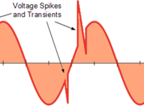
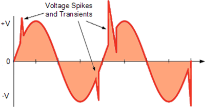
It is crucial that a staged approach is taken to prevent internally generated transients from being dispersed throughout the structure. Research performed by IEEE tells us that many transients and surges experienced are actually generated internally. A staged approach protects equipment at all levels of location and prevents damaging transients from being created and/or carried through your structure once they pass the service entrance. A typical staged approach to SPD installation would entail installation of a heavy-duty SPD at the main service entrances to handle large incoming surges, a medium duty SPD at distribution equipment; and, small, fast-acting SPDs at the point of use. This protects the equipment from the outside world, as well as any internally generated transients.
Choice of SPD equipment and its point of installation play a critical role in the efficiency of the transient suppression system. The modes of protection, let-through voltage between these modes, insertion loss, the response time of the circuit, life of circuit, and its heat dissipation capacity are deciding factors in choosing SPD devices. The point of installation should be as close as possible to the device to be protected, and the connection leads should be as short as possible. It is paramount that wire routing is short, straight, and free of kinks.
 Structural lightning protection systems are designed to protect the site from a direct lightning strike. The most common and best-known lightning protection system is the standard lightning rod, or Franklin system. The Franklin system is a series of metal rods and cables, which in the event of a lightning strike, are designed to carry the lightning energy safely to the ground and protect the facility from burning down. This type of system does nothing to protect the equipment within the structure from the secondary effects of lightning. In days gone by, this was adequate and acceptable. Today, things are different.
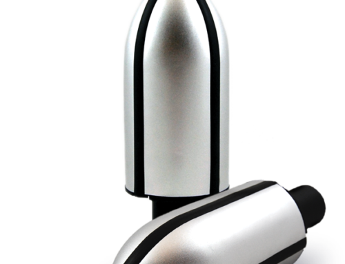
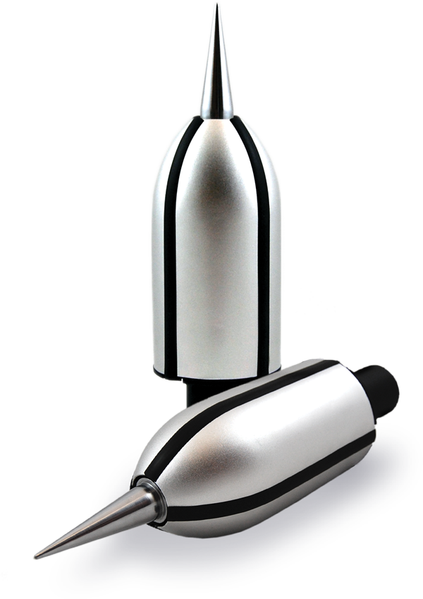
Charge dissipation technology (CDT) is a type of structural lightning protection system that has been developed over the past 30 years and is being used widely in communications and other industries. Charge dissipation, or charge redistribution, products are designed to bleed off the static ground charge that attracts a lightning strike to a structure. These devices are highly recommended for use on critical equipment sites to reduce the likelihood of a direct strike.
Using the described Three-Step Program to Success- ALLTEC’s Protection Pyramid™ method, as a guideline, this article reviews how the various lightning protection components integrate with each other and offers suggestions on how to assure the implementation of a successful system.
Traffic Control System — Unsuccessful Remote System
Before Example
The typical traffic control site has independently grounded structures forming distinct parts of a common system. Installation constraints do not allow a common grounding approach. In some cases, each mast may be grounded using a 5/8”x8’ copper clad ground rod, but with substantially more resistance at each location than desired.
The messenger support cables naturally form the site’s structural lightning protection system. If a strike were to occur on the site, it would most probably terminate on the support cables or the masts on which they are draped. Support cables are anchored to the monopole masts, but most likely do not have adequate grounding connections.This situation exacerbates the transient induction levels in messenger cables and CCTV coaxial cables, frequently causing damage in the remote electronic system enclosure.
A single 5/8’x8’ copper clad rod might form the grounding system for the remote electronic system enclosure. The physical installation may give challenges to measuring the grounding system resistance. The grounding system is not bonded to the nearest mast.
Even though the installed Surge Protection Devices (SPD) may have allowed no damage to the power distribution system, critical and expensive downstream damage to circuits may be frequently reported.
This could suggest:
Inadequate downstream surge protectors
High let-through voltage
Low response time of installed surge protection devices
Long connection cables
Inappropriate wiring of downstream surge protectors

The internal grounding system of the remote electronic systems enclosure is not structured to a single point grounding concept. This could be a cause of potential differences occurring within the electronic systems, causing damage during changes in the external ground system potential.

Surge suppressors on the main 120Vac panel incorporate SPD’s with clamp voltage of 280V (let through 160V); response time < five nanoseconds

CCTV power circuit: The 120Vac power for the six onsite CCTV cameras is provided through a parallel bus connected in series to an SPD. The SPD is neatly installed very close to the power distribution bus and about 10”-12” (lead length) from the AC panel which this SPD is supposed to be protecting from outside transients

CCTV RF circuit: RF coaxial cables from the field cameras terminate into coaxial protection modules installed on the bottom-left area of the electronic enclosure. The modules are grounded to the main ground panel on the bottom-right of the enclosure. The grounding cable lead length is very long. Clamp Voltage 6V.

Power Supply Modules and PCBs suffer from the cascade of destruction caused by transient activity.

Messenger Cable: The 120VAC, 16 pair, conductor cable regulating traffic signal switching terminates on a bus. Individual Metal Oxide Varistors (MOVs) installed on the bus provide transient suppression. This form of protection is slow, allows very high let-through voltages, creates high heat generation, causes short MOV life, and offers only single mode protection.
Traffic Control System — Successful Remote System
After System
Design and implement External and Internal Grounding Systems
Benefits of ALLTEC’s Solution:
- Limits the voltage caused by accidental contact of the site AC supply conductors with conductors of higher voltage
- Helps dissipate electrical surges and faults, and minimizes the chances of injury from grounding system potential differences
- Helps limit the induced voltages caused by lightning
- Stabilizes the AC voltage under normal conditions relative to the earth
- Aids the operation of surge protection devices
- Provides a common signal reference ground
Install an external ground ring (EGR) encircling the remote electronic systems enclosure, buried 30” deep in the soil, a distance of three feet (3’) from the enclosure. The ring and its interconnections to be made with appropriate sized (#2) tinned copper conductor. All connections are to be exothermically welded, as mechanical connections invariably degrade over time and are a significant source of impedance.
Install a master ground bus bar (MGB) made of a copper plate of an appropriate size to the grounding electrode installed through the base of the enclosure. Connect the MGB to the EGR using the same type and size of conductor used for the EGR connections with the straightest possible downward run. Connections should also be of an exothermic type.
The external ground electrode system should be designed to provide resistance below 5 Ohms. The conductor ring encircling the electronic systems enclosure is to be packed with a carbon-based ground enhancement backfill (TerraFill® – TF50), if required, to decrease resistance and impedance. The EGR will be connected to an electrolytic grounding system (TerraDyne® – TG-10S) having a minimum 10’ vertical shaft and a lockable Fiberlyte test well. This system guarantees 30 years of exceptionally low-resistance grounding in any soil type or condition. In locations where vertical digging is not possible, a horizontal electrolytic system (TerraDyne® – TG-10L) is recommended.
At the time of its installation, all metallic objects within 10’ from the system will be bonded to the external ground electrode System. Bond the EGR to the mast.
 Designing a single point internal grounding system minimizes any difference of potential that may develop between components within the system and keeps the logic grounds separate from chassis grounds. All incoming/outgoing (I/O) services are to be bonded to the MGB through a single grounding cable originating from the custom developed ALLTEC SPD where all incoming terminate. Install appropriate size subsystem ground rings (SSR) within the remote electronic system enclosure. Both SSR’s should be directly connected to the EGB as their single point ground. One ring (SSR1) to be dedicated for providing a signal ground reference (optional). Another ring (SSR2) to be dedicated for grounding equipment chassis not forming a part of the electrical system.
Design and implement Surge Protection System
Benefits of ALLTEC’s Solution:
Increased electronic infrastructure reliability
Offers a layered defense
Tailored to traffic control systems
Reduce downtime & failures
Protects equipment investment

The installation of Surge Protection Devices (SPD) is a requirement for all remote electronic enclosure sites and is essential for all facilities where microprocessor related electronics and electrical equipment are in use.
There are four major site entrances for surges that require individual attention in order to effectively protect the site and reduce the probability of transient damage:
Main AC Power
Even though the control equipment may seem to have adequate transient protection on the main AC power supply for transients entering through utility power supply cables, the let-through voltage of 160V (in this example) could be too high for downstream equipment. (ALLTEC’s method also recommends including a transient suppressor to the AC power supply to any CCTV power supply cables).
CCTV Camera Circuits
- The camera units should be powered through parallel connections mounted in the surge protection unit
- The coax cables should terminate on the coaxial protection terminal block mounted within the surge protection unit
Optical Detector Loops
- The powered data cables should terminate on a terminal block within the surge protection unit
- The terminal block should have a parallel mount surge protection unit
Messenger Cable
- The 16 conductors with 120V AC (in this example), should terminate on a bus within the surge protection unit
- The bus should have a parallel mounted surge protection unit
The point of installation plays an important role in the efficiency of surge protection devices. All connection leads need to be as short as possible so the SPDs are as close as feasible to the circuit to be protected.
ALLTEC DynaShield® custom surge suppression solutions are designed, engineered, and manufactured to meet specific site requirement parameters. In the case of this specific remote electronic system enclosure and site described in this article for Traffic Control Applications, the design requires the provision of four circuits to be terminated for transient suppression. In addition, this custom solution would have the following features integrated into a single, easy to install enclosure:
- One parallel 120 VAC SPD, connection via 30 A terminal block, Indicator LED
- One parallel 24 VDC SPD, connection via 30 A terminal block, Indicator LED
- Six BNC Coax SPDs (internal modular style)
- Internally fused protection on AC and DC portions. Fusing to be dual style–both component level and phase level -– to allow SPD removal without taking down the circuit
Sinewave tracking and full mode protection
- L-N, L-G, N-G incorporated
Design and implement Lightning Protection System
Benefits of ALLTEC’s Solution:
- Helps reduce the probabilities of direct lightning strikes at the mast
- Helps limit the induced voltages caused by lightning
Helps dissipate electrical, static charges, and faults in order to minimize the chances of injury from grounding system potential differences
- Provides a common ground reference to structures on the mast

Install copper clad external ground rod (eg. ALLTEC #5001) a distance of three feet (3’) from the mast. The ground rod having an exothermically welded 10’ pigtail and connected to the base of the mast using universal surface bases (eg. ALLTEC #2015) attached to the mast base.
Install universal surface bases on the top and bottom ends of the mast and a PVC through-the-roof conduit connector (eg. ALLTEC # 3621) on top of the mast. A copper conductor kit may be provided to connect the lightning dissipaters, camera bases, messenger support cables, and any other objects that require common bonding to the universal surface base on the top end of the mast as well as the one on the mast base.
Install TerraStat® Charge Dissipation Terminal to the mast. Installation of the CDT will drastically reduce the probability of direct lightning strike. If a lightning strike were to terminate at the CDT during a severe storm, the mast grounding system will carry the current to the external grounding system, which should be designed to dissipate the magnitude of the current efficiently, preventing any damage to site electronics.
The external ground electrode system should be designed to provide less than 10 Ohm resistance. The conductor connecting the mast to the electrode should be packed with a carbon-based ground enhancement backfill if required.
ALLTEC’s solutions resolve lightning transients related problems. ALLTEC can develop a prototype for site testing, modification, and final approval. It includes the following:
- Design and Supply of Internal and External Site Grounding and Electrode Systems
- Design and Supply of Mast Charge Dissipation and Grounding System
- Design and Supply of DynaShield® custom SPD solutions
References
- NEC 2002 National Electric Code
- NFPA 780 Lightning protection Standards
- UL 96A Installation Requirements for Lightning Protection Systems
- UL 96 Lightning Protection Components
- IEEE 81-1983 Guide for Measuring Earth Resistivity
- IEEE 1100 Powering & Grounding of Electronic Systems
- Motorolla R56 Grounding Guideline for Cellular Installations

