Telecom Grounding Systems: The Importance of the Motorola R56 Specifications

In this first part of our telecom grounding series, we will cover the implementation of low resistance, low impedance telecom grounding system from not only a practical viewpoint but as it relates to Motorola R56 specifications. The Motorola R56 specification defines standards and guidelines for communications sites.
In the United States specifically, but also around the world, many telecom carriers rely on the guidelines as set forth by the Motorola R56 specifications as well as guidelines and construction practices defined in each company’s specifications. Most major telecom carriers have a set of internal grounding specs, and these are typically a subset of the Motorola R56 specification. However, telecom carriers often add their own best-practices to their specifications and usually adopt more stringent requirements.
An example, adopting a more stringent 5-ohms “Type B” specification. Type B sites shall have a grounding (earthing) electrode system resistance goal as low as practical and not over 10-ohms. Motorola recommends a design goal of 5-ohms or less [Ref Section 4.7.4.2]. Typical Type B sites recommended for achieving under 5-ohms grounding are:
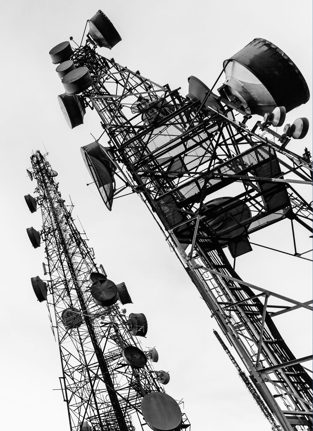
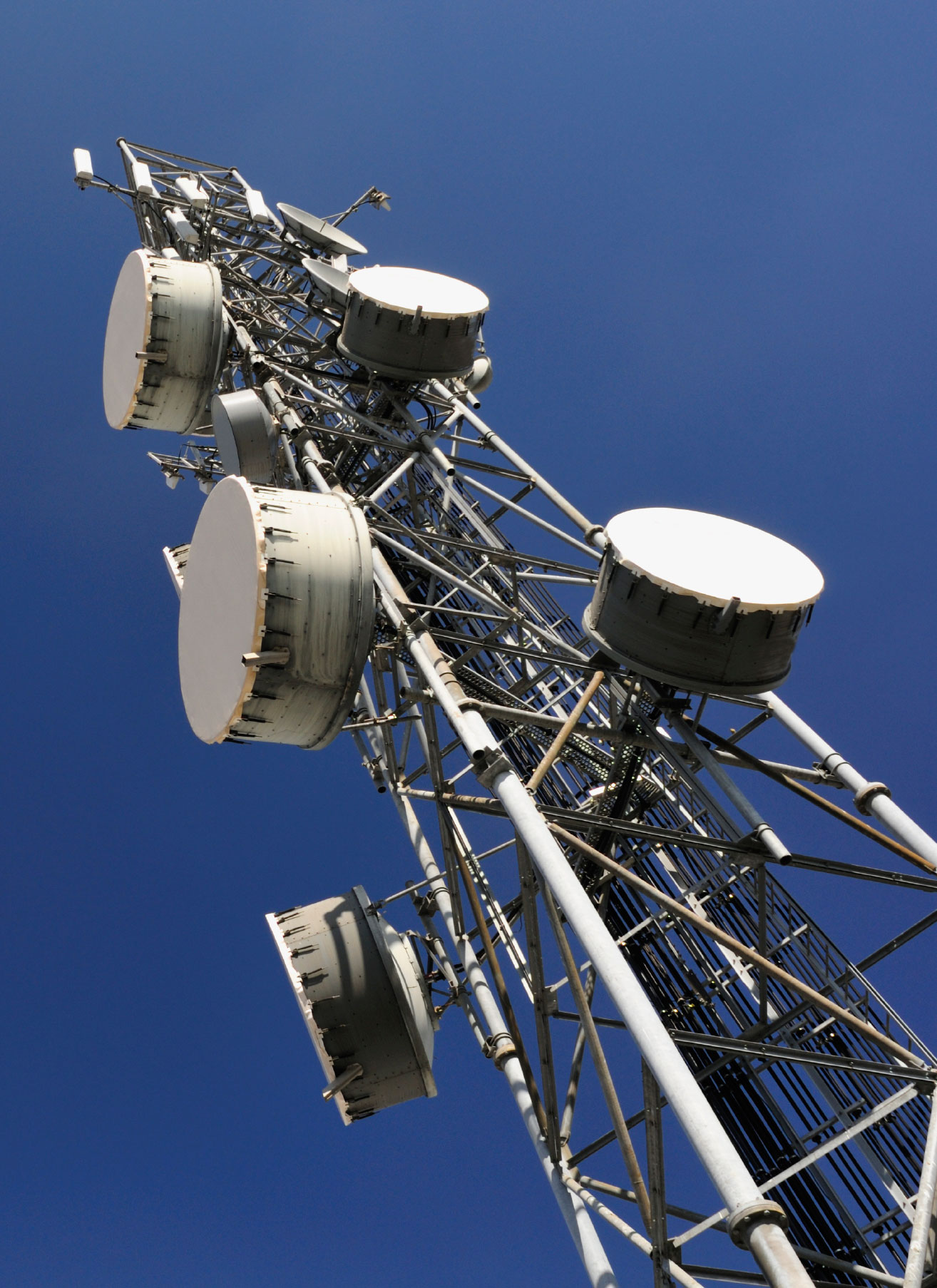
The presence of a tower on the site
911 dispatch center
Communications dispatch center
Base station and/or repeater site
Telecommunication repeater equipment installation, such as cellular, PCS, or wide-area repeater site
Large installation or multiple systems, such as telephone or electronic switches, LANs/WANs, and Mobile Switching Offices (MSO)
Critical public safety or military installation
In this series on telecom grounding, we will cover aspects of soil resistivity and ground system testing using a typical multi-function ground resistance tester. Having prior knowledge of the construction site's soil makeup, including resistivity data, down to approximately 40-foot depth, will save the contractor a lot of headaches, money, and lost time.
Many sites or co-locates never test the soil to see how well it may support a low resistance and low impedance grounding system. In part, this may be due to familiar areas within each state that reportedly have good conductive soils. Even within these known areas, however, you may run across a site that has unknown factors, such as a large rock shelf or subsurface sandstone. Generally, it is common knowledge which geographic areas have very rocky soils; thus, making it difficult to achieve results of less than a 10-ohm grounding system.
In the United States, these are known to be Northern Georgia and Alabama, throughout Tennessee, including the Appalachian Mountains, Pennsylvania, and the entire Northeast. Additionally, much of the Western United States, including Oregon and Washington, have locations where it is difficult to use a cookie-cutter grounding system design while still achieving dependable, low resistance goals. “Cookie-cutter” grounding system designs denote the basic concept of circling (counterpoise) the tower, shelter, and sometimes the fence line with a standard #2-solid-tinned wire installed below the local frost line, or at least 30-inches, as prescribed by Motorola R56.

Our engineering department reviews hundreds of cookie-cutter grounding designs each year, comparing them to soil resistivity data using specialized computer-aided analysis. Often, we determine that the basic design will do the job with no further grounding enhancements. We will cover this analyses in detail in this series. Additionally, we will discuss the Motorola R56 specification as related to the proper use of electrolytic chemical ground rods, ground plates, and backfill enhancement materials. We look forward to sharing best practices for building a low resistance, low impedance grounding system.
ALLTEC offers a strategic approach to meeting our client’s needs, the ALLTEC Protection Pyramid®. This approach looks at all aspects of a facility and works holistically to make sure all areas are protected with an effectively interlocking defense.
If you have an existing or planned facility, be sure to give ALLTEC a call or email.
We can make sure your operation is the safest possible facility, backed by our team of dedicated risk-mitigation experts. If you have a current facility or future project that needs grounding/bonding solutions, surge suppression or lightning protection, please contact ALLTEC at either 1-828-646-9290 or online-info@alltecglobal.com
