Telecom Grounding Systems: The Importance of the Motorola R56 Specifications (Part III)
In Part 3 of our series on telecom grounding systems, we will concentrate on Motorola R56 Chapter 4 – External Grounding (Earthing). There are many sections in the Motorola R56 specifications, including site design and development, communications, building and design, internal grounding, power sources, surge protective devices, minimizing interference, and equipment installation. In a later series, we will discuss charge dissipation technology (CDT) as compared to standard lightning rods (air terminals) as a superior means to mitigate direct lightning strikes.
Part 3 concentrates on fundamental grounding issues, potential misnomers, and mistakes seen in the field. We will discuss how ground rods function as well as grounding wire, grounding plates, electrolytic ground rods (TerraDyne®), low-resistance backfill (TerraFill®) and how all of these relate to the dissipation of a direct lightning strike.
Communications facilities without a tower are considered exposed to lightning unless thunderstorm activity in the area averages five thunderstorms a day per year or fewer and soil resistivity at the site is less than 10,000 ohm-centimeters. Under 12,000 Ω-cm is a good grounding environment for a standard-sized telecom compound (approximately 50’ x 50’). However, Section 4.2 goes on to say that
“communications facilities with a tower shall be considered as exposed, regardless of thunderstorm activity and soil resistivity. By their very construction, radio antennas/towers are considered exposed to the possible damaging effects of lightning. Tall structures, such as towers, buildings, and antenna masts provide a favorable discharge point for lightning strikes.”
Therefore, the construction team must take their grounding system requirements and build practices seriously Without a low-resistance, low-impedance grounding system there will be nowhere for a direct lightning strike to dissipate. The electromagnetic field will become extremely intense possibly destroying radios, electronics, and electrical sub-infrastructure.

As part of the design of a single-point grounding system of adequate wire size, ground rod length, and ground plate size, as prescribed in Motorola R56, Alltec engineers take into account all systems that need to be bonded to the grounding system.
These include:
AC power system ground
Communications tower ground
Lightning protection system ground
Telephone system ground
Exposed structural building steel
Generator ground
Underground metallic piping systems
A typical external ground electrode system specified by Motorola R56 include a shelter, tower ground ring (counterpoise), and grounding radial out to the corner fence.
However, this is not always a practical method because there may be multiple carriers on the tower with numerous shelters surrounding the tower within the compound. Therefore, it is not ideal to take prime real estate with tower grounding radials.
In most cases, a fence grounding ring (counterpoise) would be used, as this maximizes the linear feet of grounding wire without disturbing areas required for concrete shelter bases and other support structures. If the soil resistivity report indicates highly resistive soil, grounding radials may be needed at the gate to achieve a low DC resistance less than 5 ohms. Each of the ground rings, including the generator, will have two separate paths to ground that protect the ground system and equipment in the event one of these connections is breached.
Understanding the Ground Rod
Ground rods are installed around tower grounding legs. The resistance of the soil is the sum of the resistances of virtual concentric shells of earth located progressively outward from the rod, as depicted in Figure 4-5.
These shells are termed the “sphere of influence” of the ground rod. The ground rod searches horizontally and vertically out its length for a connection to the soil so that each ground rod has its piece of earth in which to dissipate electrical current. Another ground rod should not be placed within two times the length of the rod. If the ground rods spheres of influence start to overlap, efficiency will be reduced severely. R56 requires all ground rods to be UL listed. Ground rods are also required to be buried to the depth of 30” or lower, along with the grounding wire (typically a #2 solid copper, tinned wire).
If the ground rod cannot be driven to 30“, a 45-degree angle or horizontal installation at a depth of the ground wire is also acceptable. If installed horizontally, make sure it is predominantly perpendicular to the grounding wire.

Understanding the Use of Electrolytic Ground Rods
Electrolytic ground rods (TerraDyne®) are a valuable addition to the tools we use to lower ground system DC resistance and AC impedance, which affords a much better environment for a direct lightning strike to be shunted to ground. Electrolytic Ground rods should be UL listed, constructed to comply with UL requirements. TerraDyne is a large copper tube with extremely low AC impedance and are L-shaped with a length of 10 to 20 feet and a riser height as required for the specific installation (e.g. 24”- 42”).
A horizontal TerraDyne® is drilled with weep holes along its horizontal length and vent holes at the top on its riser cap. The trench dug for the TerraDyne is filled with a proprietary mixture of non-hazardous natural earth salt electrolytic product. After installing in the ground, it acts as a water pump by pulling moisture through its vented cap, weeping this moisture into the surrounding TerraFill® and soil thus keeping the device constantly in 100% contact with its environment.
As part of the grounding system at least one of these may be located at the tower grounding ring, which enables a very short and direct path for shunting a direct tower lightning strike to ground.


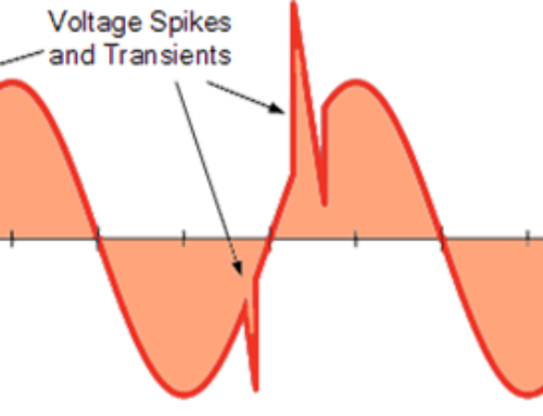
A lightning strike consists of multiple waveforms ranging from high frequencies to DC component. Because of the lightning strike’s high frequency, it tends to flow through a surface of a transmission medium, such as tower legs or down conductor. If the grounding components have poor contact with surrounding soil and the length of grounding radials are long, the overall impedance of this grounding system may also be very high. So, a vertical or horizontal ground electrode (TerraDyne®) installed near the tower base, provides the grounding system the best chance of shunting the majority of a direct lightning strike to ground.
From the R56 specification,
“the Electrolytic Ground Rods should be considered for use in grounding electrode systems covered by concrete or pavement, such as parking lots. By allowing moisture to enter, the design of the electrolytic ground rod improves the resistance of the grounding electrode system.”
A parking lot or concrete pavement keeps the soil very dry underneath and is not conducive to good grounding.
Grounding Plates
Grounding plates may be used if soil conditions prohibit the use of ground rods or if they are specifically designed for the grounding system. As the Motorola R56 specification states, ground plates shall have a minimum surface area of two square feet. A 12” x 12” grounding plate has one square foot surface area on either side and meets the minimum requirement. For poor soil conditions at telecom sites, an 18” x 18” plate is a better option as this affords 4.5 square feet, 2¼ times, the surface area. R56 also states that ground plates are to be installed vertically for better backfill contact and ease of installation. Although contractors usually find it much simpler to install them horizontally due to the use of enhanced backfill (TerraFill®) in which they are encased in trenches that are 1-3’ in width. Grounding plates may be installed between 6’-16’ apart (section 4.11.6 Shallow Topsoil Environments).
More to come in our future series on Motorola R56 Grounding Systems.


