
A “catenary” is a curve formed by a wire, metallic rop, or chain hanging freely from two points that are on the same horizontal level. Arguably, the most common use of a catenary lightning protection system is the overhead ground wire used to protect the phase conductors in power transmission lines; however, the use of catenary lightning protection for a variety of industrial and military applications is often recommended. A catenary wire may be thought of as a “horizontal” lightning air terminal.
ALLTEC’s experience in lightning protection for structures containing flammable and explosive materials, as well as for facilities where the installation of systems using traditional air terminals is difficult or impossible, includes the design of catenary lightning protection systems. Such a system may be exactly the solution for direct strike lightning protection you need.
Below we compare lightning mast protection system (case 1) to a catenary lightning protection system (case 2) in a tank storage facility using a lightning shielding analysis.

An artist’s rendition of the lightning protection system built at NASA’s Kennedy Space Center Launch Pad 39B. The launch pad was modified to support launches of Ares and Orion spacecraft. Image credit: NASA
Catenary LPS Introduction
A strike termination device is a lightning protection system component that is intended to intercept lightning flashes and connect them to a proper path to ground. Strike termination devices may consist of
- traditional air terminals (Franklin Rods),
- advanced lightning protection systems,
- metal masts,
- permanent metal parts of a structure,
- and overhead ground wires installed as a catenary lightning protection system.
For the protection of structures containing flammable vapors, flammable gases, or liquids that can give off flammable vapors; masts and overhead ground wires may be utilized to create a catenary lightning protection system. In addition, catenary LP systems are commonly utilized for any mission critical facility, complex petrochemical, or explosive storage facility where installation of traditional air terminal systems is not applicable both from installation and safety performance perspectives. Safety performance is evaluated with the requirement of a minimum distance between a strike termination device and the structure to prevent side flashes (arcing).
According to the NFPA-780 (2011) Std., the zone of protection of a lightning mast and overhead ground wire shall be based on a striking distance of 30m (100’) and defined by 30m (100’) radius arcs, concave upward (a rolling sphere).
Side Flash Calculations
To prevent side flashes, the minimum distance between a mast or overhead ground wire and the structure to be protected shall not be less than the bonding distance or side flash distance.
The side flash distance from a mast shall be calculated from the following formula:
D = h/6
Where D is the side flash distance from a mast and h is the height of the structure or object requiring protection
The side flash distance from a catenary shall be calculated as
D= L/6n
Where D is the side flash distance from a mast or overhead ground wire; L is the length of a lightning protection conductor between its grounding point and the point being calculated; n will be 1.5 where there is a single overhead wire or more than one wire interconnected above the structure to be protected, such that only two down conductors are located greater than 20′ and less than 100′ apart; or n will be 2.25 where there are more than two down conductors spaced more than 25′ apart within a 100′ wide area that are interconnected above the structure being protected.
Air Terminal Lightning Shielding Analysis
ALLTEC’s engineers utilize unique software to aide in lightning shielding analysis. Two and/or three dimension models are created to show the effective protection for a facility based on recognized standards. Two of the most common methods to perform a lightning shielding analyses is with the protection angle method and the rolling sphere method.
The protection angle method defines a protected volume provided by an air terminal with reference to the protected structures’ height. In most cases a conservative fixed angle of 45 degrees is used for a convenient approximation of the boundaries of the protected zone. This protected area is represented by a cone; everything within this cone is considered protected.
The rolling sphere method uses an imagery sphere that rolls over and around the structures to be protected. The radius of the sphere is equal to the striking distance. If the parts of the structure touch the sphere, it is at risk of being struck by lightning.
In the case of this model, the facility under consideration is comprised of three tanks housing explosive liquid with the dimensions of 61.5’ (H) × 34’ (D) and 30’ (H) × 12’ (D).
The walkway structure is extruded 4’ above the top of the tanks, and lightning protection is required to protect the facility from direct lightning strikes. Independent masts are required to be installed for an effective lightning protection system.
Lightning strike energy shall be diverted away from the tank in order to reduce the potential for side flash from direct lightning strikes.
Case I
Analysis with Independent Lightning Masts
A three dimensional model of the facility is created along with four (4) 86’ independent Lightning Masts. The lightning shielding analysis is performed with both protection angle and rolling sphere methods to evaluate the effectiveness of the installed protection system against direct lightning strikes.
As shown in the figures below, independent masts do not provide effective lightning protection system for the entire facility.
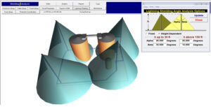
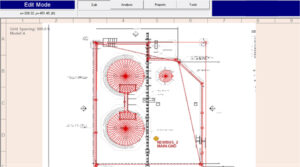
Case 1 Protection Angle Analysis for Lightning Mast Protection
This image shows the protection angle for each lightning mast as blue cones. The areas inside these blue cones is considered protected from lightning. The area in the middle that peaks out of the blue cones is not protected from lightning.
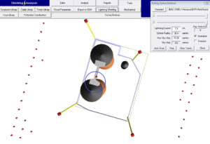
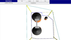
Case 1 Rolling Sphere Analysis for Lightning Mast Protection
Areas that are likely to be struck by lightning are indicated with small red dots. You can find these areas outside the square formed by the lightning masts, on the top of each lightning mast, as well as an area inside the lightning masts inside a blue circle on the image.
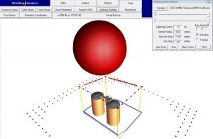
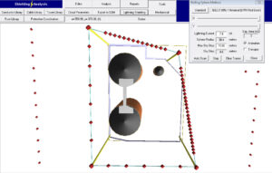
Case 1 Rolling Sphere Analysis for Lightning Mast Protection with sphere radius of 100′
In this above view image, areas that are likely to be struck by lightning are indicated with small red dots. You can find these areas outside the square formed by the lightning masts, on the top of the lightning mast, as well as an area inside the lightning masts inside a blue circle on the image.
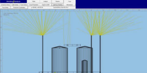
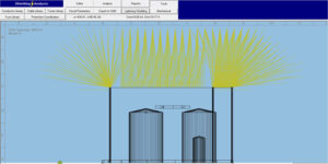
Case 1 Electro-geometric Analysis
Elevation view of the facility. Yellow lines represent likely lightning strike (8 kA) areas.
Case 2
Analysis with Catenary Air Terminal Lightning Protection
A Catenary Lightning Protection System is designed with 86’ masts above grade with stainless steel over-head ground wire. A three dimensional model of the facility is created along with installed tower and stainless steel over-head ground wire. The lightning shielding analysis is performed with rolling sphere method (100’ radius) to evaluate the effectiveness of installed protection system against direct lightning strikes.
As shown in the following figures, designed and installed independent masts with over-head ground wire will provide effective lightning protection system for entire facility.
Case 2 Wire-Frame Site Plan for Catenary Lightning Protection System
This plan view shows the addition of catenary wires to the facilities lightning masts.
Case 2 Rolling Sphere Analysis for Catenary Lightning Protection
Another view of the site’s lightning masts with the addition of catenary wires.
Case 2 Rolling Sphere Analysis for Catenary Lightning Protection
Areas that are likely to be struck by lightning are indicated with small red dots. The catenary wires provide horizontal lightning protection and are attached to the lightning masts, which are grounded.

Case 2 Rolling Sphere Analysis for Catenary Lightning Protection
A 100′ rolling sphere shows that the facility is protected against lightning strikes. Notice how the sphere does not go below the catenary wires. There are no red dots within the facility.
Case 2: Electro-Geometric Model Analysis for Catenary System
Shows the structure within the facility is protected even from 5 kA lightning strikes. Although rolling sphere radius of 100’ corresponds to return stroke current of 7.8kA, the proposed catenary LP system is sufficient to protect the facility from 5 kA lightning strikes. Notice how the yellow lines do not cross the catenary wires.
Installation & Design of Catenary Lightning Protection Systems
Contact us to find out how a
Catenary Lightning Protection system can protect your facility!
ALLTEC’s design engineers use custom lightning protection analysis of your facility to prepare installation design drawings of a complete catenary lightning protection system indicating proper placement of lightning masts/towers, over-head ground wires, down conductors, grounding system layouts, and additional accessories. Comprehensive installation drawings of the Catenary LP system are prepared as shown in the figures that follow.

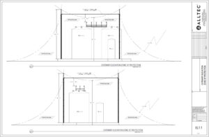
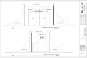
Catenary Lightning Protection System Design Examples

