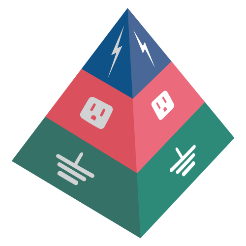
ALLTEC Protection Pyramid Surveys — A Three Part Series
If you the Introduction, you may find them by clicking on the linked text.
Grounding and Bonding is one of the most critical safety procedures to reduce the potential for electrical shocks and fires. The ALLTEC Protection Pyramid™ begins with the installation of a stable, low resistance, and low impedance grounding system and bonding all electrically conductive surfaces together. As the first tier of ALLTEC Protection Pyramid™, harmful electrical currents are safely redirected to earth and away from power, telephone lines, or data equipment using our grounding and bonding products.
Without a well-designed grounding system, all other power quality protection efforts will not function. A survey will determine how well the system stabilizes the voltage to earth during normal operation and how effectively it limits the voltage imposed by lightning, line surges, or unintentional contact with a higher-voltage line. Typically the process includes:
Site Evaluation
Specifications/code review
Testing
Written report and recommendations

Step 1: Site Evaluation
Site evaluations help you understand the issues related to the inefficiencies of the grounding/earthing & bonding system. Grounding/earthing & bonding surveys must be planned to harmonize with the expectations of what will yield desired results with available funds. Therefore, the best way to start is with a site evaluation:
Collect information on types of damages experienced or anticipated by the facility, and create a prioritized outline of survey requirements.
- Study existing site plan drawings, site grounding system layouts, one-line electrical riser diagrams and one-line data riser diagrams.
- Review the physical site to identify zones of activities, main electrical panels, grounding system test locations, and bond points.
Recent studies indicate that as much as 80% of all failures of sensitive electronic equipment attributed to poor power quality may result from inadequate electrical grounding or wiring on the customer’s premises or from interactions with other loads within the premises.
–Wiring and Grounding for Power Quality EPRI CU-2026, March 1990
Step 2: Specifications/code review
The grounding survey team needs to be experienced with different types of grounding applications and have a firm understanding of relevant codes and standards. Otherwise, the ground system survey may not result in the optimal recommendations. Ground system resistance requirements should be interpreted for different facilities by different standards.
One standard doesn’t fit all applications or facilities ground resistance requirments. A review of the facilities environment and requirements will determine the standard applied.
For example, NEC article 250.56 requires a 25-ohm ground system resistance with the installation of a single ground electrode for any service entrance electrical system to protect against electrical hazards. It also states that an additional single electrode should be installed if the goal resistance is not met. Thus, NEC safety requirement may be satisfied by the installation of two (2) electrodes, resulting in a much higher resistance than 25 ohms.
However, for critical microprocessor based instrumentation or other power quality sensitive applications, this resistance may not be sufficient. Additionally, grounding and bonding requirements for flammable operations may differ from standard electrical codes. Grounding system resistance for high voltage applications should be low enough to meet step-and-touch safety voltage criteria per IEEE-80 standard.
Many standards and references are used when conducting a grounding survey, including:
NFPA 70 – National Electrical Code (NEC)-2014
NEC Article 250 – Primarily for Safety from the use of Electricity
NFPA 780 / UL 96A – For Lightning Protection System Grounding
- IEC 62305/NFC Standard – International Standard for Lightning Protection Systems
IEEE 80 – For Ground System Design of High Voltage Substation
IEEE 81 – IEEE Guide for Measuring Earth Resistivity, Ground Impedance, and Earth Surface Potentials of a Grounding System
IEEE 65 – For Ground System Design of Generating Stations
IEEE 142-2007 (Green Book) – Grounding of Industrial and Commercial Power Systems
Motorola R56 – For Telecom Tower applications
FAA and Military Handbooks on Grounding & Bonding – For Commercial installation including Telecom Towers
Company and Equipment Manufacturer’s Standards
Step 3: Testing
After developing an understanding of the facility and its needs a site-specific test plan is created. Typical actions include:
Visual inspection of external grounding system and internal bonding system
Fall-of-potential tests per IEEE-81 standard
Clamp-on resistance and leakage current testing
Point-to-point testing as required to evaluate the resistance of existing grounding and bonding systems
4-point testing (Wenner Method) per IEEE-81 standard
Soil resistivity data, parameters, and study
Two-layer soil model
Specialized tests according to industry


Step 4: Written Report & Analysis
On-Site Survey & Testing, Data Analysis and Computer Modeling should yield a Survey Report and supporting documentation containing observations, testing and data analysis, and site photographs as needed. Reports should include
Survey Report
Testing results
Listing of grounding & bonding compliance
If needed, report on required upgrades to cover noncompliance
If you have an existing or planned facility, be sure to give ALLTEC a call or email.
If you have an existing or planned facility, be sure to give ALLTEC a call or email. We can make sure your operation is the safest possible facility, backed by our team of dedicated risk-mitigation experts. If you have a current or future project that needs grounding/bonding solutions, surge suppression or lightning protection please contact ALLTEC at either 1-828-646-9290 or online-info@alltecglobal.com


