There has been a rapidly growing trend for petroleum, water/wastewater and chemical industries to utilize Fiberglass Reinforced Plastic (FRP) storage tanks. FRP storage tanks are typical for these industries due to their non-corrosive properties as compared to standard metal storage tanks. Even though FRP storage tanks are not metal, they are still exposed to lightning and are a potential fire hazard. The non-conductive property creates additional resistance to fast lightning current impulses and generates intense heat at the point of impact. Fires starting at a single FRP tank can engulf an entire facility.
Even in the case of an indirect lightning strike, it may also be considered that an unequal ion discharge rate between an insulated FRP tank and a nearby grounded/bonded metallic structure can cause the development of a difference of electrical potential, thus, creating a spark which could lead to a tank explosion and fire.
Available lightning strike data related to tank farms is neither comprehensive nor readily available, with most reports consisting of media releases such as the four events shown to the right.
In June and July of 2014, lightning-sparked fires destroyed saltwater disposal facilities at three locations in North Dakota. Over 440 such sites exist in North Dakota alone. Production tanks associated with well sites are used principally for enhanced oil recovery and saltwater disposal. Reportedly, there are 144,000 such wells in the USA. Downtime and recovery costs from potential lightning strikes can be very expensive and have possible safety consequences for personnel, strategic infrastructure, and critical storage tanks.
With appropriate use of lightning protection methods; replacement costs, losses due to operational shutdown, and safety liability issues can be minimized. An engineered mix of structural air terminals, equipotential bonding, and grounding can protect fiberglass reinforced plastic storage tanks. This paper describes the risks associated with FRP storage tanks to direct lightning strikes and provide guidance to protect facilities from direct lightning strikes and/or secondary lightning transients.

Midland Martin Count Line, TX
09.16.2013

Gradford, TX
06.25.2014

Watford City, ND
09.31.2014
Lightning Risk Analysis | Electro-Geometrical Model
Approximately 1,800 thunderstorms are in progress somewhere on Earth. About 100 lightning bolts hit the ground each second. Historical lightning data has been compiled to create an Isokeraunic map showing the statistical average number of thunderstorm days per year for any area of the world. A three-dimensional model was developed for a typical FRP storage tank facility. Lightning attachment points are calculated and displayed visually using an electro-geometric model applied to a three-dimensional representation of the facility.
The standalone direct lightning strike probability should not be the only consideration for effective lightning protection design and implementation for FRP storage tank facilities, as indirect lightning strikes may also cause sparking or flashover to vapor and/or contents that are stored within the facility.
Of course, the modelled facility may have a greater or fewer number of tanks than any existing or proposed FRP storage tank facility under consideration. The relationship between lightning strike probability and the number of tanks is very linear, and for a good approximation the change in risk doubles each time the number of tanks doubles. This allows for some useful calculations. For example, if an owner/operator maintains fourteen times the number of tanks shown, in Texas, then they can expect one tank to suffer a direct strike every year. Since it cannot be known beforehand which individual tank will be struck, it is highly suggested that all tanks should be protected.
The probability of a standalone direct lightning strike should not be the only consideration for effective lightning protection design and implementation. Indirect lightning strikes may also cause sparking or flashover to vapor and contents that are stored at a facility.
Even when a modeled facility has a greater or fewer number of tanks than an existing or proposed FRP storage tank facility under consideration, the probability may still be calculated. The relationship between lightning strike probability and the number of tanks is very linear. To calculate an approximation, the change in risk doubles each time the number of tanks doubles. This allows for some useful calculations. For example, if an owner/operator maintains fourteen times the number of tanks shown in Texas, then they can expect one tank to suffer a direct strike every year. Since it cannot be known beforehand which individual tank will be struck, it is highly suggested that all tanks should be protected.
The probability of a direct lightning strike to the storage tank facility was determined with consideration of its relative location. The following chart shows the total number of expected strikes per year for the modeled facility located at two different Isokeraunic values.
| State | Isokeraunic Value | Total number of expected strikes per year |
Direct Lightning Strike probability to the Facility |
|---|---|---|---|
| Florida | 100 | 0.124 | Once every 8.0 years |
| Texas Kansas Oklahoma |
60 | 0.0743 | Once every 13.5 years |
Expected Lightning Strike Frequency for Different Isokeraunic Values

3-Dimensional View

Lightning Strike Analysis for 15 kA Return Stroke Current
Lightning Protection & Grounding System Solutions
ALLTEC has observed that most fiberglass storage tank facilities implement bonding and grounding sufficient for electrostatic charge dissipation. Discharge of accumulated static electricity from a storage tank or another charged object of different voltage to ground can cause a fire or an explosion if it takes place in the presence of readily flammable materials or combustible vapor and air mixtures. ALLTEC recommends that existing bonding and grounding at FRP Battery/Tank Farms be inspected and any non-compliances to NFPA 77 “Recommended Practice on Static Electricity” should be identified and corrected. Proper bonding guidelines should be followed per the recommended practices.
It is important to note that bonding and grounding implementations sufficient for electrostatic charge dissipation are not adequate for lightning protection grounding systems. Even a ground resistance of 1 MΩ is adequate for static grounding. [Ref. section 3.2.6.2 IEEE 142]

Approx. #2 AWG jacketed wire bonding sufficient for electrostatic dissipation but not appropriate for lightning protection. Note bond lug to interior “carbon veil.”

Fiberglass Tank CDT Lightning Protection Design for FRP
Existing bonding and grounding systems at the FRP storage facilities should be enhanced by implementing a code compliant lightning protection bonding and grounding. All metal ladders, overhead piping, and vents should be adequately bonded and grounded. Properly designed and installed lightning protection is essential because closed top metallic tanks may have flammable atmospheres at their vents, and fiberglass tanks receiving a direct lightning strike may rupture violently. To best provide the high level of lightning protection required by fiberglass tank facilities, a mix of technologies and a selection of globally accepted standards should be used.
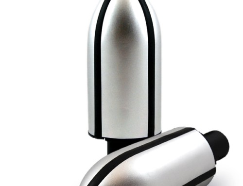
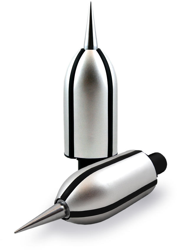
For instance, API-2003, “Protection Against Ignitions Arising out of Static, Lightning, and Stray Current: Appendix C,” describes Charge Dissipation Terminals (CDT) as one of the lightning protection technologies used to mitigate the path of an incoming lightning stroke. Also, NFPA 780, IEC 62305 and other standards for lightning protection describe minimum requirements for lightning protection system design and installation. Designs utilizing Charge Dissipation Terminals meet or exceed those standards while offering the enhanced performance provided by CDT technology.
A low impedance ground system resistance of less than 10Ω is recommended for all FRP storage tank areas. The US Military Handbook for Lightning Protection (MIL-HDBK-1004/6) and IEC 62305 std. recommend having a minimum of 10Ω ground system resistance for an effective lightning protection system (LPS). Metallic elements, particularly those in flammable zones, should be bonded together and adequately grounded using a “single point ground” methodology.
ALLTEC can model an existing, new, or proposed ground system by creating a soil model using soil resistivity test values. The resulting data is entered into specialized integrated grounding software that will accurately calculate soil resistivity at various depths. ALLTEC provides an array of grounding products, including TerraDyne® electrolytic ground electrodes, TerraFill® ground enhancing backfill, and the TerraWeld® exothermic welding system to supply and install grounding systems. An example of a typical 10Ω ground system design for effective dissipation of lightning energy is shown in the following figures. In the case study, approximately 950 feet of conductor and four (4) Electrolytic Ground Electrodes are modeled.

Grounding Plan for FRP Storage Tank Facility
| Approx. Soil Resistivity Value | Ground System Resistance | Ground System Components |
|---|---|---|
| ≤ 76,000 Ω-cm | ≤ 9.93 Ω | 950’ of ground conductor and four (4) electrolytic ground rods |
| ≥ 80,000 Ω-cm | > 10 Ω | The ground system design of 10 Ω can be achieved with low resistivity backfill material using trenched ground conductor and additional electrodes |

3D Ground System Model
Surge Protection Solutions
In addition to proper grounding and bonding, it is crucial to install SPDs at key points throughout the tank farm’s AC power distribution system. A comprehensive network of quality surge protective devices (SPDs) protect critical equipment loads from lightning and non-lightning related surges and noise anomalies.
A cascaded network of SPDs designed to work in tandem with each other should be installed on 480 V main distribution panels and motor control centers (MCC) to protect against externally generated surge activity. They should also be installed at 120/208 V UPS panels and other sub panels that supply power to critical equipment loads to protect them from surges originating from within the tank farm.
It is also advisable to individually protect equipment loads that are electrically located further than 50 feet from a protected point within the electrical distribution. These SPDs should incorporate common mode suppression components to shunt lightning induced surge current to the electrical distribution’s ground circuit. They should also employ normal mode suppression circuits to distribute internally generated surge current between power phases and between the phase and neutral conductors on the AC power service. They should also be equipped with a first order noise filter to attenuate disruptive transient related noise voltages to equipment safe levels. Moreover, careful consideration regarding protecting equipment control and data interfaces should be deliberated wherever their operational disruptions would cause any significant downtime or work slow-downs. At the very least, all control and data lines entering and exiting a structure should incorporate proper SPD protection.
Likewise, any medium voltage transformer or rotating machine load that has either suffered from premature insulation breakdown or is deemed to be vulnerable to this type of damage should be individually protected by quality stand-alone station class arrestor fortified SPDs – even if they are already equipped with normal or heavy duty class surge arresters.
Implementing these recommendations will bolster Tank Farm equipment surge and noise immunity levels to the highest possible thresholds to extend their operational life expectancies, increase their efficiency levels, and reduce their maintenance, repair, and replacement costs.
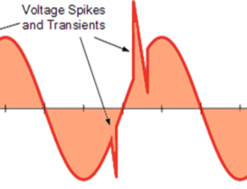
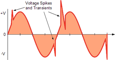
Transient Sources and Its Impact
Generically powerline noise is defined as low amplitude (< 50 V) disturbances distinguishable by an identifiable frequency pattern. On the other hand, a transient surge is a momentary burst of energy whose duration extends into the millisecond range. A typical surge waveform is characterized by rapidly rising voltage and currents that reach their peak values in the low microsecond ranges and decay to half those levels in under a millisecond.
Noise disruptions are differentiated by frequency patterns. High-frequency noise spectrums are classified as radio frequency Interference (RFI), while low-frequency noise patterns are labeled as Electromagnetic Interference (EMI). While surge anomalies are far more likely to interrupt equipment operation and damage electronic hardware, transient induced noise interference can also disrupt sensitive equipment operations.
Transient surges are categorized as either externally generated impulses, such as lightning-induced electrical energy burst, and as internal or manmade transient irregularities. A decaying oscillatory ringing transient (noise) attributed to power factor correction activities is an example of the latter anomaly. The most intense surge events are lightning generated. However, surges originating elsewhere can also be at high voltage levels.
Lightning-induced surges initiated by direct lightning strikes can produce momentary voltages up to 75 kV at their point of impact.
Indirectly coupled surge impulses originating from nearby lightning activity, on the other hand, generate voltage bursts up to 25 kV.
Power source generated surge activity initiated by power factor correction capacitors and from load shedding operations can produce surge voltages up to 15 kV.
Internally generated capacitive load generated transient activity, ground potential differences, and the power cycling inductive loads can each produce surge voltages as high as 10kV.
Therefore, it is crucial to install SPDs at key points throughout the tank farm to adequately protect the equipment loads from the surge as mentioned above threats.
ALLTEC Protection Pyramid®
As an ISO 9001:2008 registered full-service company, ALLTEC specializes in engineered solutions that reduce the risks associated with direct and indirect lightning strikes as well as diminishing the hidden effects of surge events. Based on decades of knowledge and experience, ALLTEC’s recommendations advise the best methods for risk mitigation and ultimately apply these evaluations as comprehensively engineered solutions. Our organization maintains one of the most knowledgeable and experienced technical staffs in the world.
ALLTEC’s Oil & Gas solutions aim to:
Protect critical facilities, equipment, records, and assets
Provide a safe working environment for personnel
Reduce the risk of downtime and lost revenue
Reduce vulnerability of interdependent critical infrastructures and build a disaster resilient enterprise
Minimize liability and maintain competitive pricing
The ALLTEC Protection Pyramid® is the framework used to visualize, design, and implement comprehensive facility protection using grounding, surge suppression, and lightning protection. When applied correctly, it’s three-tiers create a robust, stable system capable of withstanding direct and indirect effects of lightning strikes as well as internally or externally generated transient voltages.

Are you considering a lightning risk mitigation plan? If so, please contact us.
Rev. 20141003

