
Solar farms are just big fields covered with conductive material. They’re almost asking for a lightning strike, which can damage or destroy solar panels, inverters, and other critical equipment. So it’s no surprise that lightning activity and surge-related over-voltage abnormalities are identified as leading causes of solar project downtime.
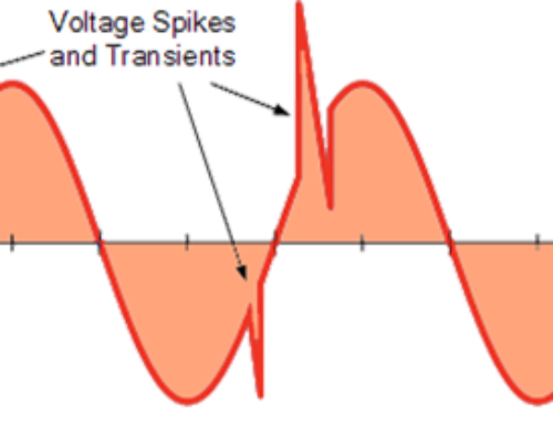
Lightning can be destructive even when it’s not a direct hit. Indirect lightning events generate an electromagnetic force that induces overvoltage and transients on AC and DC power conductors and data lines.
The good news is solar owners and developers can protect their investment from the fallout of lightning strikes. Engineers at ALLTEC, a global manufacturer and installer of grounding and other lightning protection technologies, have identified methods to bolster a project’s ability to withstand lightning-related hazards using a three-step process called the ALLTEC Protection Pyramid. While there is typically no code requirement for solar farm owners to install lightning protection, there are internationally recognized standards and methods to determine the requirement of lightning protection systems, and it’s a bright idea to take action. The pyramid provides guidance.


The ALLTEC Protection Pyramid begins with the installation of a stable, low resistance and low impedance grounding system to bond all electrically conductive surfaces together. The installed grounding system should provide safety step and touch voltage criteria appropriate for a power generation facility. After providing a stable grounding system, it is important to properly install a surge protection device (SPD) system. Finally, a well-designed structural lightning protection system can be installed.
Below are more details for each tier of the protection pyramid to help establish smart grounding, surge suppression and lightning protection on solar arrays. A full white paper on the Protection Pyramid is available here.
Comprehensive soil resistivity measurement is the first step in designing a solar grounding system. Soil resistivity is a measure of how much soil resists the flow of electricity. A proper test will use the Wenner four-point method, which corresponds to IEEE Std. 81. The Wenner test uses four probes spaced at equal distances to measure how much electricity is conducted between them through the soil. The distance between the test probes results in soil resistivity data at the equivalent depth. It is considered to be the most reliable soil resistivity test.
After obtaining a thorough understanding of how soil conducts electricity and obtaining multilayer soil resistivity test results, specialized grounding software can help model the best grounding system for an array. By using a computer model, designers can complete a comprehensive fault analysis. Safety step and touch voltage evaluation can also be performed for the entire project, including solar panels, inverter and transformer stations and the perimeter fence layout.

In addition to proper grounding and bonding, it is crucial to install both AC and DC surge protection devices at key points throughout a solar site to protect panel module circuits, inverter stations and critical control circuits at the combining switchgear box. It is recommended that a comprehensive network of quality SPDs be installed throughout the solar farm’s AC and DC power distribution to protect critical circuits against hardware damage and from operational disruptions resulting from lightning and non-lightning related transients.
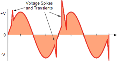
Although lightning-generated transients are by far the most intense surge events, surges originating elsewhere can be at high voltage levels as well. For example, lightning-induced surges initiated by direct lightning strikes can produce momentary voltages up to 75 kV at their point of impact. Indirectly coupled surge impulses originating from nearby lightning activity, on the other hand, generate voltage bursts up to 25 kV.
Additional equipment that should be outfitted with a cascaded network of SPDs include:
Each line combining equipment
Inverter input circuit
Inverter output
Medium-voltage input to the step-up transformer in the photovoltaic combing switchgear
Critical data circuits and UPS in a switchgear room
All control and data lines entering and exiting a structure

The National Fire Protection Association (NFPA 780) and International Electro-Technical Commission (IEC-62305) standards suggest solar developers take stock of lightning risk to establish a baseline for lightning protection systems. In other words, it’s the developer or owner’s responsibility to conduct a cost-benefit analysis and decide what type of lightning protection should be added to an array.
The level of risk can be ascertained by comparing the probability of direct lightning strike to the solar farm—what’s known as a regional isokeraunic level (number of flashes/sq. km/year)—and the facility’s risk parameters. After human safety, the risk associated with loss of power production (continuity of service) should be the first concern in determining the need for an effective lightning protection system.
Regardless of risk, it’s unfortunately true that external lightning protection system design and installation is not a common practice for solar farms, large or small.
Where solar arrays are installed on residential or other rooftops, lightning protection as described in NFPA 780, Chapter 12, is a useful reference. However, lightning protection of solar arrays by traditional Franklin rod systems is still subject to concerns regarding effectiveness, shadow effects, installation cost and appearance.
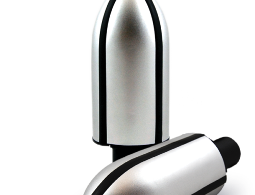
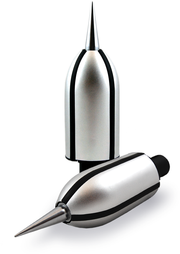
As an alternative to the traditional Franklin rod system, early streamer emitter (ESE) type lightning air terminals can protect a solar farm. The TerraStreamer ESE terminal provides large protection zones as per National French standard NF C 17-102. TerraStreamer ESE terminals can be installed on independent masts with radial lightning protection ground systems with single-point reference to the electrical grid. This configuration provides necessary protection zones, effectively dissipating lightning energy to the ground and helps to insulate the solar panels and inverter stations from damage. The other benefit of this system is that there will likely be a significantly lower cost of labor and material to install the entire system as compared to a traditional Franklin rod system.

