Telecom Grounding Systems: The Importance of the Motorola R56 Specifications (Part II)
In Part two of our telecom grounding system series per the Motorola R56 Standard, we will deal with a few concepts.
First, we’ll look at soil resistivity. Soil resistivity relates to how conductive the usable soil is below the telecom compound area.
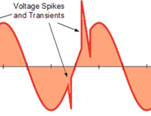
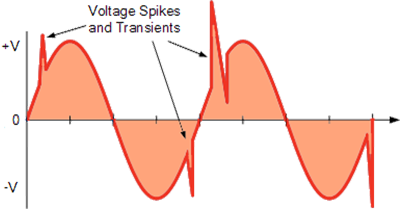
Next, we’ll examine why we are not only interested in DC resistance of the ground system but why ground system impedance also matters. We use the ground system not only for fault-protection and equipment reference but also for the dissipation of anywhere from 5 kA to up to 100 kA of current during a direct lightning strike.
Additionally, we’ll look at the practical matter of installing a grounding system in poor soil conditions.


So, the lease company has turned out a site; the carrier has completed their design for the type of tower; and, equipment is to be installed. Let’s look at a typical 60′ x 60′ compound with only one equipment shelter to be installed at this time. This site is called a raw-land build (we’ll discuss a co-location build in a bit). The carrier has established their contractors who are going to manage/build the site. Before proceeding with foundations, the next step should be a . Wenner 4-Point Soil Resistivity test.
However, some carriers go directly to building the tower site without having soil resistivity data from the 4-Point. Soil resistivity test. There are a few reasons for possibly skipping this test and installing the cookie-cutter ground system as shown on their site plans. If the carrier/contractor is aware of local soil conditions–for instance, the tower is being installed in the middle of Lancaster County, PA with some of the deepest and richest soil anywhere–it’s a good guess that installing approximately 250 of #2-T wire will be sufficient to bring the ground DC resistance under 5 ohms.
It gets very complicated and expensive when this assumption does not pan out. Because once the ground wire is installed on the compound, it becomes challenging to get any accurate data readings from a 4-point soil test with copper already in the ground. The 4-point soil test may take a half-day to perform, start to finish, but it can alleviate many headaches before breaking ground. And, a soil test is relatively inexpensive to perform even if you utilize an outside contractor to perform this test. IEEE Std 81 7.2.1 notes that is difficult, or impossible, to obtain a useful approximation of soil resistivity from sample measurement and recommends the Wenner 4-Point Soil test method.
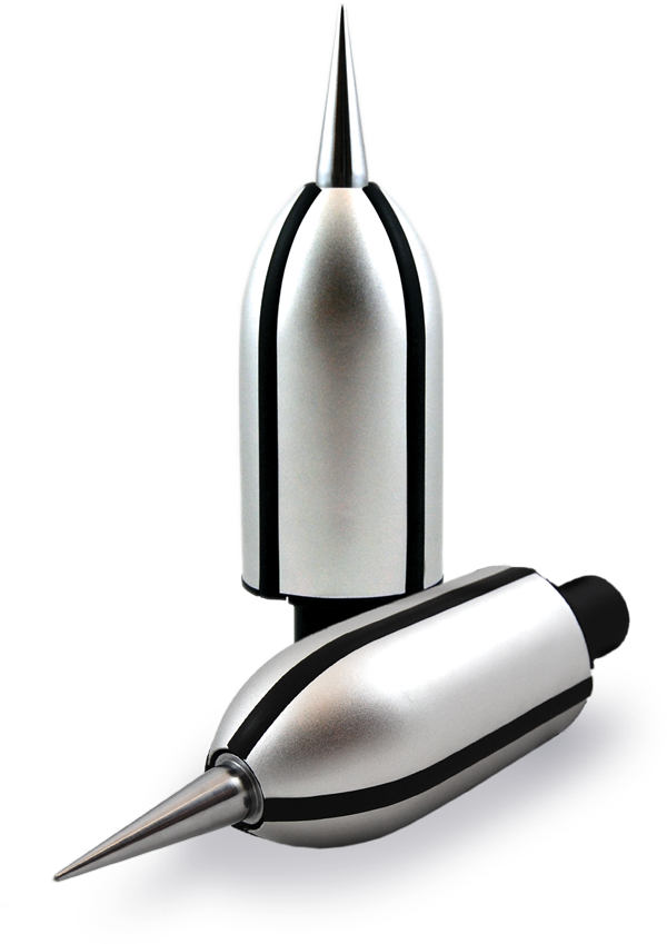
A Wenner 4-Point Soil Resistivity test is performed using a specific meter. Meters are available from several companies, such as AEMC, MEGGER, FLUKE, and others. The test consists of hammering four metal probes into the ground, spaced according to Motorola R56 shown in table B-2.
A 4 Point soil test meter is tied to each of these probes, as instructed by the meter manufacturer. Current is injected into the soil first at 40-foot pin spacing, and progressively smaller pin placements down to 5-foot spacing. The meter takes voltage readings on the other 2 probes and results are displayed on the LED. This test is performed optimally, 5 times: on each of the 4 compound borders and once diagonally across the compound. The data, as taken directly on the readout of the meter, in ohms, is recorded in a table–see table B-3
Once all the data is recorded from each run, you may convert these ohm values to the label, ohm-cm. The formula is ρ = 191.5 x A x R, where A is the distance between rods, and R is the resistance, in ohms, from the meter. If the data is not converted, ALLTEC engineers will convert these readings to ohm-cm when they receive the soil resistivity test before starting on an enhanced grounding system design. The table B-3 will give us the results shown in table B-4 for all depths recorded.
| Rod Spacing | Soil Depth |
|---|---|
| 5′ | 5′ |
| 10′ | 10′ |
| 20′ | 20′ |
| 30′ | 30′ |
| 40′ | 40′ |
TABLE B-2 SOIL DEPTH MEASURED AS A FUNCTION OF ROD SPACING
| Locations | Spacing (test depth) | ||||
|---|---|---|---|---|---|
| 5′ | 10′ | 20′ | 30′ | 40′ | |
| 1 0f 5 | 1960 Ω | 1150 Ω | 627 Ω | 257 Ω | 153 Ω |
| 2 of 5 | 2030 Ω | 904 Ω | 684 Ω | 271 Ω | 166.2 Ω |
| 3 0f 5 | 642 Ω | 216 Ω | 173 Ω | 113.9 Ω | 86 Ω |
| 4 0f 5 | 330 Ω | 206 Ω | 166.5 Ω | 124.5 Ω | 91.2 Ω |
| 5 0f 5 | 300 Ω | 195 Ω | 155 Ω | 130 Ω | 95 Ω |
TABLE B-3 MEASUREMENTS
| Locations | Spacing (test depth) | ||||
|---|---|---|---|---|---|
| 5′ | 10′ | 20′ | 30′ | 40′ | |
| 1 0f 5 | 1.88 M Ω-cm | 2.12 M Ω-cm | 2.40 M Ω-cm | 1.48 M Ω-cm | 1.18 M Ω-cm |
| 2 of 5 | 1.94 M Ω-cm | 2.29 M Ω-cm | 2.62 M Ω-cm | 1.56 M Ω-cm | 1.28 M Ω-cm |
| 3 0f 5 | .61 M Ω-cm | .61 M Ω-cm | .67 M Ω-cm | .76 M Ω-cm | .70 M Ω-cm |
| 4 0f 5 | .32 M Ω-cm | .47 M Ω-cm | .60 M Ω-cm | .75 M Ω-cm | .73 M Ω-cm |
| 5 0f 5 | .29 M Ω-cm | .37 M Ω-cm | .60 M Ω-cm | .75 M Ω-cm | .63 M Ω-cm |
| Average | 1.0 M Ω-cm | 1.17 M Ω-cm | 1.39 M Ω-cm | 1.0 M Ω-cm | 0.9 M Ω-cm |
TABLE B-4 TEST RESULTS IN Ω−cm
Let’s interpret the data we accumulated at this site. As you can see, this is extraordinarily poor soil for installing a grounding system. Looking in the table, and understanding that your typical telecom ground wire will be installed 30” in depth, or 6” below the local frost line, we can see that the 5 foot depth averages 1,000,000 ohm-cm (very high). And, across all depths of recorded data, the soil is very poor for grounding. It is not unusual to see these types of data when you look at where many cell towers are located, at the top of a knob or mountain where it is typically very rocky.
We use several methods of grounding to try to bring down the overall ohm value using a combination of long ground radials installed down access roads, 1/8” grounding plates, enhanced TerraFill® backfill material surrounding the ground wire, and TerraDyne® electrolytic ground rods–which are electrolyte filled copper tubes, sometimes installed to depths of 100′ or more. TerraDyne® acts like a water pump and continually pulls moisture out of the air and leaches this water into the surrounding TerraFill® low resistance backfill material. Because of the long ground radials associated with this poor soil, a heavy piece of copper, like TerraDyne, helps bring down the overall ground system impedance to assist in dissipating a direct lightning strike to ground.
To avoid a scenario of installing an inadequate ground system in marginally poor soil conditions, it is always advisable to perform a Wenner 4 Point Soil Resistivity test. If the results average out to be above 12,000 ohm-cm, present this data to ALLTEC and our engineering department will review and advise your best course of action. You will save money and downtime in the future before the digging begins.


A co-location is an established telecom compound with one or more carrier’s shelter already present. You want to add your shelter. Most carriers want to see their grounding system achieve under 5 ohms before tying in the two connections from their shelter ground ring (counterpoise) to the established tower counterpoise. Many times this is difficult to establish since there is already a ground wire present often located on the perimeter of the fence line. ALLTEC can advise on these types of sites, especially if the original soil report and geophysical report are available for examination.
The best way to determine if you’ve met your grounding system requirement of under 5 ohms is to perform a 3-point fall-of-potential test prior to the electrical company neutral being installed. In future segments, ALLTEC will cover this test and more.
If you have an existing or planned facility, be sure to give ALLTEC a call or email.
ALLTEC offers a strategic approach to meeting our client’s needs, the ALLTEC Protection Pyramid®. This approach looks at all aspects of a facility and works holistically to make sure all areas are protected with an effectively interlocking defense. We can make sure your operation is the safest possible facility, backed by our team of dedicated risk-mitigation experts. If you have a current facility or future project that needs grounding/bonding solutions, surge suppression or lightning protection, please contact ALLTEC at either 1-828-646-9290 or online-info@alltecglobal.com

